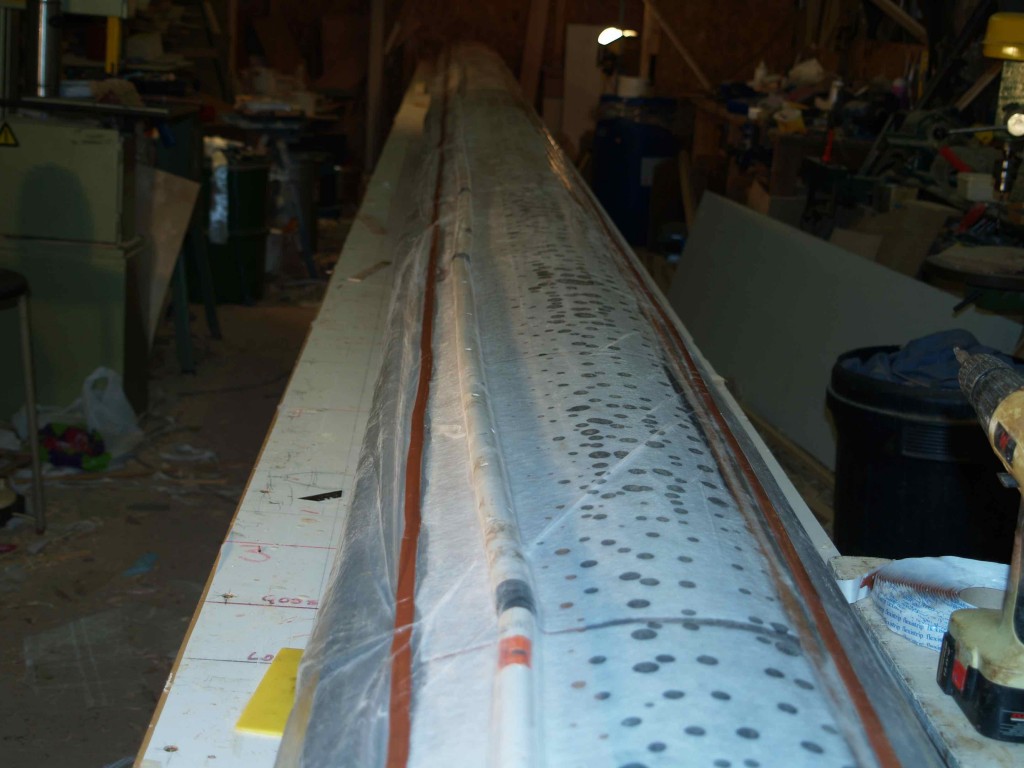
A couple of months of limbo dancing under the long table in the workshop has left us quite weary and glad to have pulled the mast together without major mishap.
With the shear web (4mm ply and spruce edges) glassed both sides and reinforced where necessary, we fix some 20mm plumbing overflow pipe to its forward side and run the mouse lines up through the pipe. We achieved this using a clever trick that I had read about but never tried, by attaching thin nylon cord to a tampon and sucking it through the pipe with the vacuum cleaner. It worked a treat! In fact it was such fun that we did it a second time!
Laminating the sides
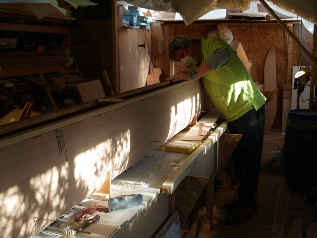
The ply sides had to be laminated next on a mould that was fitted precisely to the straight edge of the table, so that we could clamp and screw a piece of 3 x 1 along the table edge to pull the ply down into shape. We did not use a vacuum bag for this process as we considered that battens, clamps and simple surface tension would be enough to hold the layers together and the vacuum process would not make it possible for us to get the extreme curve we needed. Having scarfed the panels to full length the technique went as follows:
- Coat the sides of the panels to go together with epoxy, then lay one panel on top of the other, starting at one end and laying down carefully so no air becomes trapped.
- Shuffle the whole thing onto the mould, aligning and gently clamping the back edges.
- Screw a 2 x 1 batten in position on the ‘crest’ of the bend, the screws holding the ply firmly down onto the mould at each station.
- Work gradually along the leading edge (sticking out over the edge of the table), pushing it down to be held in place by the 3 x 1 batten. (We covered all battens with parcel tape for release and to allow the plies to slide downwards as they were pulled into the curve.) Long screws meant that the batten could be in position before the glue-up started and gently pulled in as we tucked the ply down.
- Then go back to the trailing edge and press the plies down onto the mould , clamping at 150mm intervals. This is necessary because the leading edge curve pushes the wood off the mould. We avoided placing individual screws as this would result in dimples where the thin ply is held down locally.
After leaving the laminate to set on the mould for a couple of days we measured carefully for the taper at top and bottom and cut the laminated ply precisely to shape, remembering to bevel the leading edges where they would come together (and remembering left and right sides!). Then the sides were copper wired together and the shaped leading edge timber glued in position, pulled down by more copper wires inserted through the wood and the table. At this stage we checked that the spread of the sides was just enough for us to be able to lower the shear web into position. We had previously shaped the mould to achieve a sort of opened-up mast profile about 10mm oversize at the shear web and 100mm wide at the trailing edge. A layer of 300gsm glass then covered the leading edge to halfway up the sides. Most of this area did not have to bend very much, if at all, so stiffening it created no problems for later. The rest of the inside had 165gsm cloth for lightness.
Sheave boxes
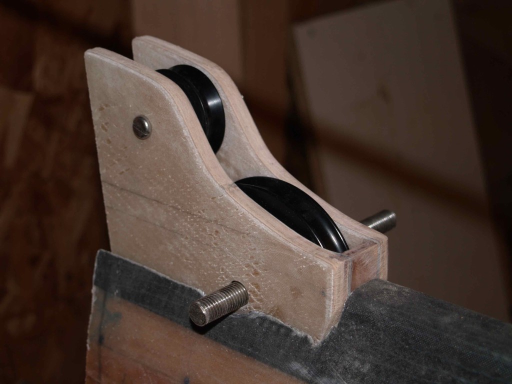
Before closing the trailing edge of the mast we had to fit the sheave boxes, constructed from 9mm ply with stainless sides and heavy glass reinforcement . The sheaves I have chosen are the Antal tulip sheaves, specially designed for rotating masts. They are much wider than conventional sheaves and have a gentle splay to protect the rope from chafing against the edges. Cutting and chiselling the apertures has to be done while leaning over into the ‘trench’ as we came to know it. It is awkward work but has to be done accurately and strongly reinforced to take the expected loads. We placed 5mm thick glass on the top and bottom lips of the opening.
The shear web is lowered into position to rest on stiff wires that go through the sides. We used these wires at the leading edge glue-up stage to check alignment and twist. The idea is to have the shear web in a straight line up the mast. At last we were ready for the closing-up. Halyard runs also had to be moused, and I fitted a short length of pipe down the inside leading edge for an electric cable to supply an all-round green light about a metre below the masthead. (As permitted by Colregs Rule 25(c) I shall fit red over green all round masthead LED lights – you can’t have a tricolour on a rotating mast! If we end up looking like a Christmas tree, so much the better for visibility.)
Struggling to get it straight
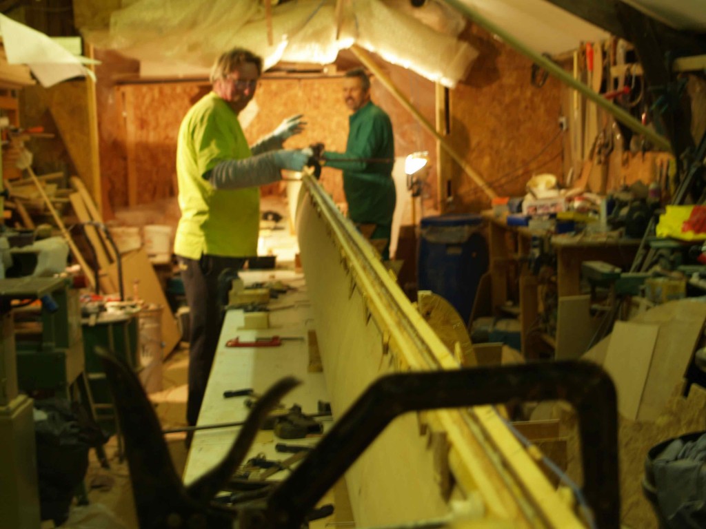
Gluing up the shear web and trailing edge took three of us 5 hours. Much of the time was spent carefully buttering the surfaces with epoxy. We lowered the web suspended on its side by strings into the gap and turned it into final position, checking it for longitudinal alignment. Then we started the trailing edge squeeze. It came together without too much difficulty, and the bottom half of the mast lined up well with the string we had stretched along it. But the top half was something of a nightmare. Perhaps it was because we did not trust the accuracy of our previous work, but we somehow managed to make it a real struggle, eventually settling for an error of about 2mm along a section of about 500mm. It is always hard to keep up standards when you are exhausted, and I was unhappy that we had left it not quite perfectly straight. In the event this hardly mattered as we planed and sanded the trailing edge back before adding the UD carbon.
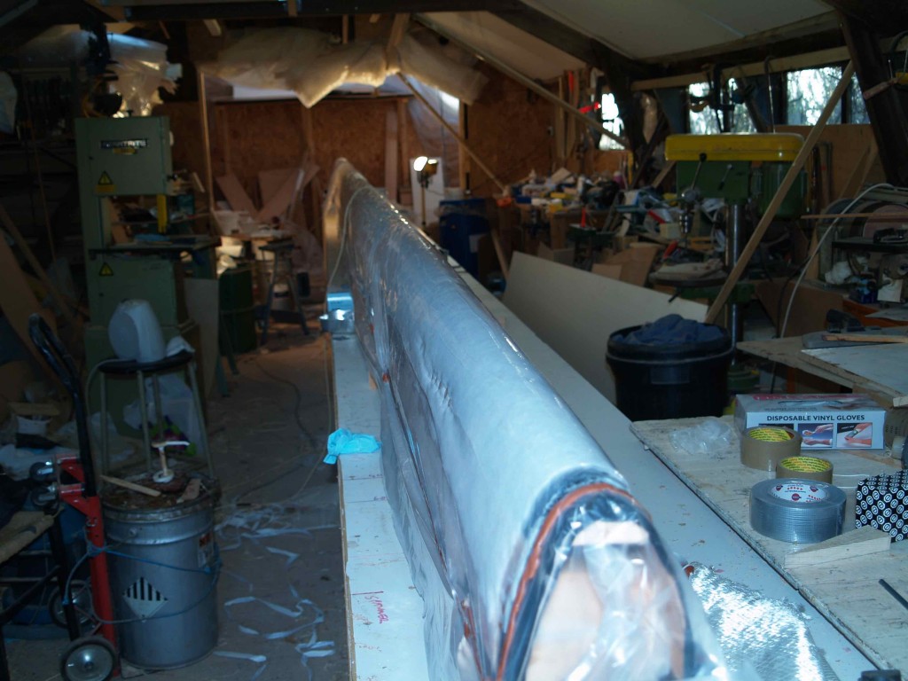
The core of the mast was now complete, so we extracted the copper wires using a soldering iron to soften the epoxy and sanded the leading and trailing edges. We applied the trailing edge carbon first, then leading edge and finally each side. They all had to be done separately because the carbon has to be vacuum bagged to consolidate the matrix and remove air bubbles. I had consulted with wingmast expert Nick Barlow earlier in the year, and he provided me with a lay-up schedule that would result in the correct stiffness and strength. Essentially the unidirectional carbon does most of the work because it reaches full tension before the wood or glass, so there has to be enough of it on the outside to cope with all the major loads. Twisting loads are taken by the wood and the relatively small amount of biaxial glass that holds the mast together. The compression loads, (up to 9 tonnes!) are again largely taken by the carbon, which needs to be held in column by a layer of glass wrapped around the outside.
Bearing in mind these big numbers, we were happy to put 7 layers of carbon on each axis, spreading them carefully so they were as straight as we could get them. Around the sheave boxes we glued extra to transfer loads. We used Ampreg 22, a higher specification resin than the multi-purpose 106, and better for wetting out laminations. But in the cool conditions it was necessary to try to keep temperatures up as much as possible. This resin will benefit a lot from post-curing, which will be done when the glass reinforcement has also been applied. Ideally I need to raise the temperature to 40 degrees, almost impossible in a chicken shed during winter in Devon! It might have to wait until spring for the baking.
The mast is now starting to look good, lovely and straight despite my earlier misgivings. Before Christmas I shall finish the detail reinforcement, the masthead, hounds, gooseneck and foot, and get the sailmaker to bounce up and down on it. The spreaders will need some thought and will probably be carbon over a foam core, fixed permanently to the mast. Where the compression forces are all resolved into the stainless ball hitch on the main beam I am paying particular attention to providing enough strength and spreading the loads where possible. For me much of the interest in learning how to build a composite mast has been in trying to understand the forces involved and working out how to make something strong enough to cope with them but as light as possible. We hope to keep the all-up weight of the mast under 70kg, which looks realistic at this stage.
There seem to be a number of competing ideas about how to construct composite masts, some opting for the stressed skin approach and others making use of a structural spar to carry the loads. My original plans from Kurt Hughes favoured the former, but I ended up choosing the latter because it is easier to construct and somehow seemed more logical. As carbon has become more available designers are relying on it more to carry the major loads, so the wooden core of the mast becomes less critical and the two approaches start to merge. The shear web in my spar would not be stiff enough on its own to make a good mast, so it needs the structure of the skin to keep it in column. One thing is clear: if carbon is used, you need to use enough of it and place it as far as possible from the centroid, i.e. on the outside of the mast where it can do most good. I think the designs that use just a little carbon to stiffen the shear web misunderstand how the different materials behave. The loads on masts are incredibly high and one needs always to bear this in mind.
Synthetic rigging – combining the old with the new
Standing rigging is a real issue for rotating masts. Loads on the shrouds are high and can be snatch loads, the worst of all for causing failure in stainless wire. There has been much recent development of synthetic rigging, mostly by the cost-no-object racers with stuff like PBO and carbon rod. But a product of real significance to ordinary multihulls is Dynex (and a further development, Dux). This is produced by an Icelandic company called Hampidjan and marketed in Canada by Precourt Systems, who have also given thought to the terminations. Dynex is modified 12-strand Dyneema rope, a type of polypropylene, buoyant, stronger than steel and five times lighter. It was developed for the Icelandic fishing fleet, and can be easily spliced to retain 90% of rope strength. Although it exhibits creep with permanent loading, it is ideal for shrouds on wingmasts where loads are intermittent and the resting position is relatively slack. There is an interesting article by an Australian multihuller who has used it for his fixed rigging, accessed through the website www. hampidjan.is . Marlow now also sell D12, a similar unsheathed Dyneema product. The key to its use seems to be to specify a size that has an ample reserve of strength. 11mm Dynex will take about 19 tonnes, so that should be plenty!
The issue with any synthetic rigging has always been how to terminate it. Precourt manufacture aluminium deadeyes and solid thimbles that are needed for use with Dynex. They also sell soft hanks for synthetic forestays, although I personally think the risk of chafe is too great on this critical stay. Of interest are the complete rigging kits offered for Farrier trimarans. On my boat the deadeyes will be lashed to the composite chainplates, essentially a stainless tube strongly glassed onto the hull, with smaller diameter Dynex. I like the idea of combining traditional seamanship techniques with up-to-the minute products. It is simple, non-corroding, easily adjusted and replaced without specialist help, and no more expensive than stainless wire rigging. But interestingly Precourt do not recommend Dynex for pre-loaded stays like diamonds. Here they prefer the stainless.
It has been an interesting adventure in mast construction, and all this hard work will result in a spectacular spar, but it is not necessarily a cheap option. The standard of workmanship required is higher than for the main construction, and the risk of failure carries greater consequences. It would not be worth doing for a fixed mast, or if one is not prepared to go the whole hog with the carbon. But boy is it lovely to look at!! I can’t wait to see how it sails.
www.precourt.ca
www.hampidjan.is
