I have described before how progress on a project of this size never seems to be linear, but is all long slogs and sudden comings-together. These last couple of months have seen some real forward leaps as the boat starts to take shape. I have also been spending big sums on essentials and trying to resist the fancy gizmos…
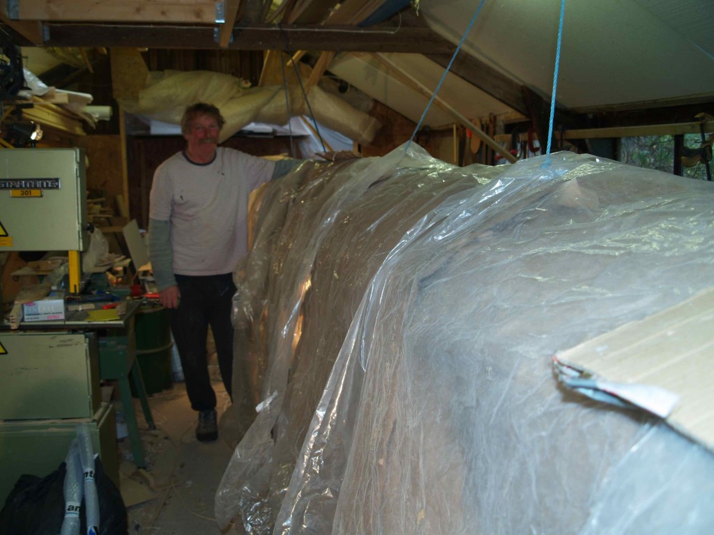
On the construction front, the main and aft beams are finally glassed and largely done. The aft box beam needed reinforcement where the mainsheet track runs across and glass cloth everywhere else. Like all external surfaces, it received a further 3 rolled-on coats of epoxy for protection. Extra glass was also added internally to support the mainsheet loads.
At about this time I read in a copy of Yachting World (October 07) a report on the initial sea trials of Hugo Boss, a brand new Open 60 racing monohull. The session had to be cut short as the mainsheet track started to pull its bolts through the deck …! Andy and I were amazed that professional builders could make such a mistake, even on a weight-saving racing boat. If that could happen in the Solent, what would fall off in the Southern Ocean? We will be using strips of stainless with 2 holes in them as a sort of double washer joining up adjacent bolts inside the beam. If this track is going to come loose, it will have to take the whole of the top of the beam with it!
The forward beam has finally received its rounded nose of cedar strip and glass, making the boat suddenly appear somehow more complete and purposeful. On the front of this will go the anchor box and connection for the forward walkway, as well as the attachment for the front netting.
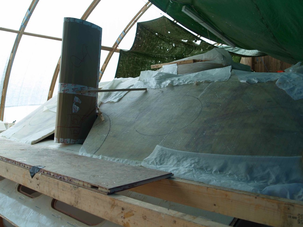
With the completion of the cabin roof, we swiftly installed the interior floor and the cockpit floor. Of course both of these have to be removeable for now, so they rest on composite ledges and are supported by some 4 x 2 braces. But their installation has meant that the inside can be walked across, and we have tried out the rough seating arrangement using upturned cardboard boxes! I will tackle the cabinets and seats when the weather gets colder, as it will be relatively easy to heat the cabin interior.
But before the cold and dark months I wanted to get 2 more major components out of the way. We have now almost completed the front netting beam and started construction of the mast itself. The beam is essentially a smaller, more heavily-built version of the mast, so it has given us a good opportunity to try out the techniques that will be critical for the success of the mast itself.
The netting beam
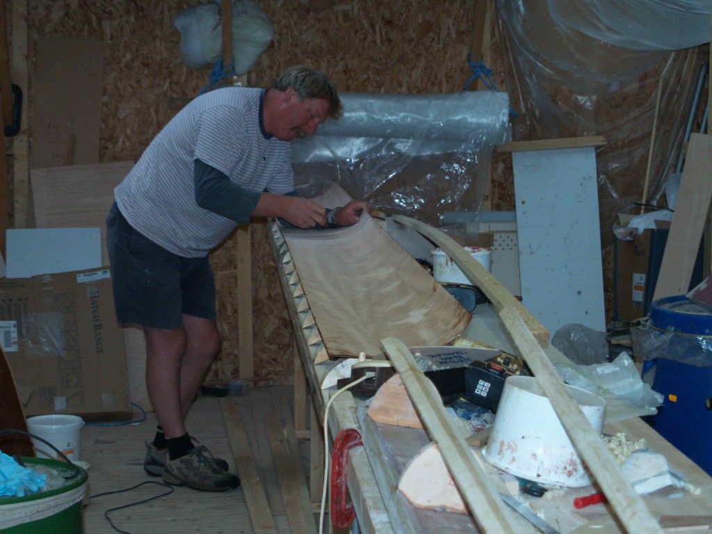
The beam has a shear web of glassed 6mm ply, doubled in the centre and at the ends of the beam. Bulkheads are spaced along it at the critical load points (for the forestay and seagull striker) and to convey the compression loads across the structure. Softwood leading and trailing edge timbers complete the skeleton. The skin is made up of 2 layers of 1.5mm ply, scarfed and laminated to shape over a simple mould. Making the scarfs on very thin sheets of ply called for a new technique, in which we constructed a small vacuum table to hold each sheet in place while the router cut the gradient. With thicker ply it is normally possible to stack the sheets and grind them all together. Unfortunately the thinner ply is, the easier it buckles and distorts. The mould shape was derived from the template, allowing for the two joined halves to remain open enough to get the frame in but closing tightly against the bulkheads when the trailing edge was closed. We checked the fit by making a small sample length.
With the 2 halves of the shell now joined by a strip of glass at the leading edge, we were able to lower the skeleton frame into place and glue the entire assembly together. In order to be able to squeeze the trailing edges together for screwing, it was necessary to have some purchase for the clamps, so strips of scrap softwood had been glued to the outside on each side. These were sawn and sanded away once the epoxy had set, and the whole assembly glassed with some unidirectional and biaxial cloth.
Working out the moments
Spars like this are specified according to ‘moments’, usually expressed as inches or centimetres to the power of four. Masts and booms have an XX and YY number, which tell a mathematician what bending properties the spar has in two axes, and reassure the rest of us that the thing is stiff enough. In the case of my plans the moments are, unhelpfully, expressed in inches to the fourth, which don’t seem to convert to the equivalent centimetres – a real trap for the unwary. Fortunately for us, the alloy boom arrived from Z Spars, and the plans have the major axis of this roughly the same as the moment for the netting beam.
It only remained for us to do a practical test, which is to compare the deflection using a known weight. If the beam is too bendy, then it needs more reinforcement. So that is how I came to be sitting on the middle of the beam on top of the bench with Andy checking the deflection caused by my 75kg! Our test has shown that the beam does indeed need more reinforcement to bring it up to spec.
But what are the loads on a front netting beam? Obviously there is the upward pull of the forestay, which for my boat will be a maximum of about 2 tonnes. This is pulling upward right in the middle of the beam, and would easily snap anything but a hefty girder if there were no countering downward force. The seagull striker acts like a one-sided spreader to exert sufficient downward force to keep the beam in column. But with the wires from the striker to the ends of the beam at about 30 degrees from horizontal, the load on them is more like double the downward force. (My maths is not up to all this, but I can understand the principles.) It all translates into some very large compression forces in the beam itself. These forces come into play only when the forestay gets loaded up, at rest they are much more modest, thank goodness.
So we have used 8mm stainless plates to attach the seagull striker wires directly to the ends of the beam where it bolts onto brackets on the hulls. The plates are bolted onto the shear web against a bulkhead, to spread the loads across the whole spar. At the moment the beam weighs about 25kg, without the stainless plates, and will doubtless be a few kg more with the necessary stiffening. It will be similar in weight to an alloy section, but it looks terrific!
At last the mast
While doing all this technical stuff on the beam, we have also started on the mast components. Our 40ft long table (glued to the floor) bisects the workshop, and means we have elaborate manoeuvres to perform each time we need a tool from the other side. And once a piece of wood is made up into the full length with scarfs etc. it cannot easily come off the table without being vulnerable to twisting and breaking under its own weight. We have now built the shear web – much lighter than the beam one – and the leading and trailing edge timbers, scarfed up from the best quality spruce. All the processes take far longer than on the shorter beam, and I am sure we are getting fitter just walking up and down the length of the table so many times! At this stage all the internal fittings have to be considered, because only a trained mouse will be able to get at them later. The wiring conduit (20mm water pipe), sheave boxes, spanner tube, spreader reinforcement and other items will all be installed before the mast is closed.
As with the beam, the mast will have a double skin of 1.5mm ply, but will use carbon fibre on the outside to give strength and stiffness at minimum weight. The carbon will take most of the loads up and down the mast because it has far less give than wood or glass, so it is important to add enough carbon to be able to manage these loads. 7 layers of 300gsm x 100mm wide tape will go up each side, with a similar amount fore and aft. It would be fair to call this a carbon spar with a wood internal mould. At a cost which will work out about £1000 cheaper than an alloy extrusion, and a lot of fun rising to the challenge of building it, why not? (Er…answers on a postcard to the Editor!)
Show time!
The Southampton Boat Show conveniently coincides with the season for special offers on sails, so I decided to order the main at a 20% discount. Westaways Sails have got my order, and one benefit of them being local is that they will come up and measure the mast before cutting the sail. I was quite amused to be asked how much bend there would be in the spar, as I assume that at a chord of 15” and with all that carbon fibre there will be almost none. Perhaps we will all sit on the mast and check it!
Probably the most important thing will be to ensure that they cut the sail with the draft well forward, given that the mast itself forms part of the aerofoil. Although there is a confusing array of modern cloths available, it was clear to me that it came down to a choice of a laminate sail with either Pentex or Kevlar fibres and a taffeta scrim for ease of handling. This was borne out recently in Erik Lerouge’s articles for MR. Although at the moment I have opted for the Kevlar, it may be that I change my mind and go for the Pentex as being less brittle and probably longer-lived. I will take the sailmaker’s advice on this one.
In quick succession I have been purchasing a whole load of necessities:
- the autopilot, essential to have the item itself to be able to build it in
- portholes for the cabins – it’s getting too dark inside!
- the boom, because I need the gooseneck to be able to fit it to the mast
- cushion fabric, so my daughter can start on making up the covers as soon as I have the foam.
- the engines, because like the sails they were on special end-of-season offer
- the electrics and batteries, because the man on the Merlin stand warned that world lead prices had risen sharply and he was expecting large increases in battery prices soon.
Well, perhaps the last one was a salesman getting a bit carried away, but as I have to build things in, there is nothing like having switch panels and batteries to hand to be able to fit them. The engines are a good case in point. I realised that my slightly vague plan of hoisting the engines up into the corner of the cockpit would not quite work with the bulky FT9.9 Yamahas. But a little shopping around on the internet yielded a very good offer on FT8s. These have similar characteristics to the bigger versions, but are a little more compact and several kilos, not to mention pounds sterling, lighter. As the plans call for 6HP engines, they should still be more than adequate. And with some careful construction the hoist should work just fine. The casing will provide a corner seat in the cockpit, and lift off for lowering the engines.
It is not the first time that I have moaned about the lack of detail on the plans, and I often read about others having similar difficulties, so why do designers persist in leaving out vital details? Is it because they simply expect us all to know them, or because they don’t actually have a good solution themselves? I have spent, and continue to spend, hours designing and redesigning details that really should have been done by the designer himself. Engines seem to be depicted just as a box with a horsepower number in it and a couple of vague notes about making sure the tiller bars do not get fouled by them. And yet it is crucial to get their installation right. They need to lift right out of the way or dragging a propeller will take knots off the boatspeed, and yet they must be capable of being properly immersed so that cavitation does not occur in lumpy conditions. The lifting mechanism needs to be capable of being locked in the lowered position for reversing. And they should be mounted not too far aft otherwise they can adversely affect the balance of the boat.
I cannot complain about things like the front beam, which I opted to build instead of purchasing a ready-made extrusion. But a little more attention to detail from the designer would mean I didn’t have to revisit my rusty O Level Maths and Physics quite so often!


